 English
 русский
 Deutsch
 日本語
日本語
Specifying a gas spring correctly starts with one number: the force it must deliver at the required stroke position. The real calculation is a moment balance, not a simple weight estimate. If you choose a gas spring by only matching the weight of a lid, door, or seat, the unit is likely to be either too weak to hold the part open or so strong that the part slams upward. This article explains the force equation, the variables a gas spring force calculator needs, a worked example, and the practical mistakes that appear on the shop floor.
Content
- 1 Start with the basic gas spring force equation
- 2 How a gas spring force calculator models your application
- 3 Worked example: sizing a gas spring for a heavy lid
- 4 Common mistakes in gas spring force calculations
- 5 From calculation to real product: matching the force to the application
- 6 Why validate calculator results with a manufacturer
Start with the basic gas spring force equation
The theoretical output force of a gas spring is F = P × A, where P is the internal nitrogen pressure and A is the effective piston area. The manufacturer normally rates this force at a defined point in the stroke, usually with the rod fully extended. That rating is called F1.
F2 is the force measured with the rod fully compressed. The difference between F1 and F2 comes from internal friction and the change in gas volume as the rod moves into the cylinder. In a typical unit, the difference is 10 to 20 percent, and that matters. If you use only one nominal force, the spring may feel too soft near the end of compression or too hard near the end of extension.
What F1 and F2 mean in practice
For design work, always request both values when you ask a supplier for a quote. A gas spring that meets the calculated F1 but has an unusually high F2 will behave differently when a person pushes the moving part down. This is especially important in seating and access panels where controlled motion is part of the user experience.
How a gas spring force calculator models your application
Key inputs you need before running the numbers
A force calculator is only as good as the inputs you give it. Before calculating, collect the following:
- Weight of the moving part, including handles, hinges, and any attached components.
- Location of the hinge or pivot axis.
- Distance from the pivot axis to the center of gravity of the moving part.
- Position of the gas spring mounting points on both the fixed frame and the moving part.
- Stroke length and the opening angle you want to reach.
- Expected operating temperature range.
The moment balance equation
The calculation is a moment balance around the pivot axis:
Fspring × dspring = W × dcg
Fspring is the force delivered by the gas spring, dspring is the perpendicular distance from the pivot axis to the spring centerline, W is the weight of the moving part, and dcg is the horizontal distance from the pivot axis to the center of gravity. Because dspring and dcg change with the opening angle, you need to check at least three positions: closed, partially open, and fully open. The position that requires the highest spring force sets the rating you should specify.
For a two-spring installation, divide the required force between the two units. Add a safety margin of about 10 to 15 percent to cover seal wear, pressure tolerances, and variations in production.
A typical online calculator assumes simplified geometry. If your mounting points are not symmetrical, use the calculator as a starting point and hand-check the critical position in your CAD model.
Worked example: sizing a gas spring for a heavy lid
Consider a lid whose center of gravity is 300 mm from the hinge when the lid is closed. The lid weighs 150 N, and you plan to use two gas springs. The table below shows the required force per spring at three positions based on a simple moment balance.
| Lid position | CoG lever arm | Gas spring lever arm | Force per spring |
|---|---|---|---|
| Closed (0°) | 300 mm | 120 mm | 187.5 N |
| Partially open (30°) | 260 mm | 128 mm | 152 N |
| Fully open (60°) | 150 mm | 140 mm | 80.4 N |
The closed position demands the highest force. Multiplying 187.5 N by a 15 percent safety margin gives 216 N per spring. This means the specified F1 for each spring should be at least 216 N. A force calculator that asks only for the moving weight will miss this number, because the moment depends on the lever arm, not just the weight.
In practice, also check whether the gas spring will be installed with the rod pointing up, down, or sideways. Orientation changes friction and internal lubrication, so the same F1 can feel stiffer in one mounting position than another. If the calculated value does not match any standard product, a custom unit with adjusted gas pressure is usually a better answer than changing the mounting points.
Common mistakes in gas spring force calculations
Even with the right formula, small errors can lead to a spring that is too weak or too aggressive. The mistakes below are the ones we see most often in production drawings and send-back requests.
- Using the full weight of the moving part instead of calculating its moment about the hinge. The weight alone does not tell you the required force.
- Assuming the gas spring force is constant over the entire stroke. F1 and F2 are different, and the lever arms also change.
- Checking only the closed position. The force demand can be lowest there if the spring mounting geometry changes, so always check at least three angles.
- Adding an oversized safety factor. A 30 percent margin may make the spring so strong that a light operator cannot close the lid, especially if the spring is mounted close to the hinge.
- Ignoring temperature effects. Internal gas pressure changes in proportion to absolute temperature, so a unit rated at 23°C can deliver noticeably more force in direct sunlight or in a hot workshop.
One typical case we saw involved a 200 N cover that was fitted with a 500 N spring. The installer used the cover weight directly without considering the short lever arm of the spring. The cover flew open so quickly that small operators could not control it. Recalculating with the real lever arm pointed to a 300 N unit, and the problem disappeared.
From calculation to real product: matching the force to the application
A force value is only the starting point. The correct unit must also have the right stroke, end fittings, damping behavior, and mounting geometry for the product you are building.
In seating applications, the load is not a static lid but a moving person. The balance between F1, damping, and locking force determines whether the seat travels smoothly or jerks. If you are working on bar stools or similar height-adjustable seating, bar stool gas springs should be matched to the expected user weight range and the height adjustment travel. Our matching gas springs to bar stool design and weight requirements guide covers these variables in more detail.
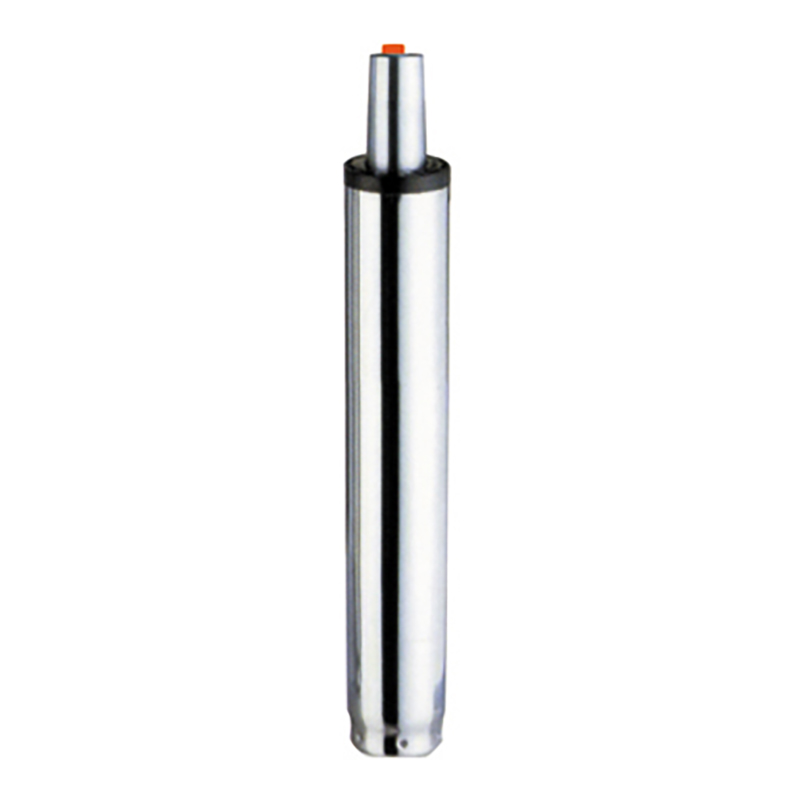 Bar Stools Gas Springs Suppliers, Factory - Changzhou Andefu Gas Spring Co., LtdAndefu is China Bar Stools Gas Springs Suppliers and Factory, Custom Bar Stools Gas Springs for sale, The ADF-243 series bar stool gas sp...View Product →
For cabinet doors, machine guards, and access panels, a support gas spring gives a predictable lifting force with a simple mounting layout. In these products, the closed-position moment balance is usually the number that defines the F1 rating.
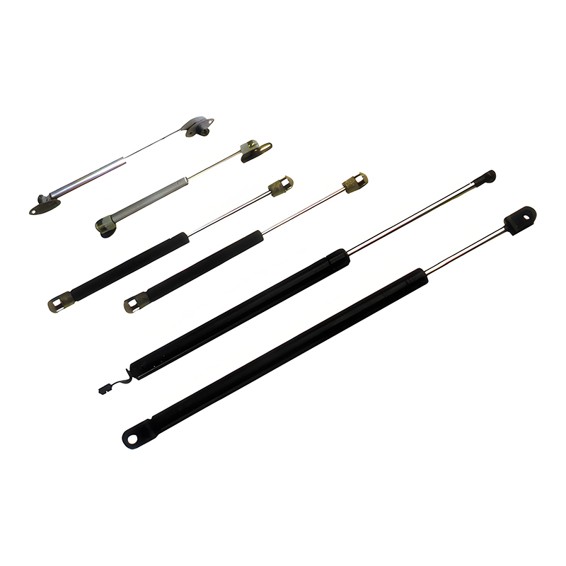 Gas Spring Support Manufacturers, Gas Spring Lift Support SuppliersADF is Gas Spring Support Manufacturers, Gas Spring Lift Support Suppliers and Gas Strut Lift Support Factory in China, offer Gas Strut L...View Product →
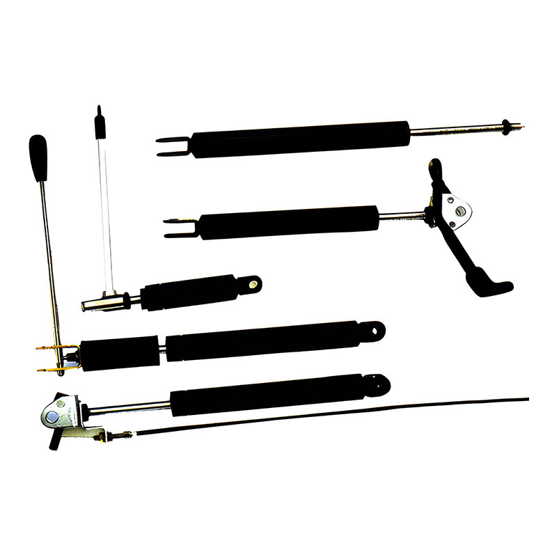
When the moving part must hold at an intermediate position, such as a monitor arm or a maintenance hatch, a lockable gas spring provides position locking anywhere in the stroke. Verify the locking force at the point where the load is highest, not just at the fully closed position. For a deeper comparison, see our adjustable locking gas spring selection guide.
 Lockable Gas Spring Manufacturers, Locking Gas Springs SuppliersChina Adjustable Locking Gas Springs Manufacturers, Lockable Gas Springs Suppliers and Factory, ADF offer Custom Lockable Gas Struts, Adj...View Product →
The mounting position itself changes the effective lever arm, so the same force value can feel different on a short, stiff arm versus a longer, softer one. Always verify the actual distance from the gas spring centerline to the pivot in your CAD model before ordering.
Why validate calculator results with a manufacturer
A calculated F1 value is a theoretical number, not a final specification. Real production units are affected by rod diameter, seal friction, oil fill, mounting brackets, and the exact position of the attachment points. This is why a manufacturer with in-house testing can save you time and rework.
At ADF, we develop gas springs and cylinders from customer drawings or samples, inspect every process step, and support both OEM and aftermarket projects. With 15 production lines and a team of more than 130 people, we are set up to handle custom stroke lengths, special end fittings, and force values that do not always match standard catalogs.
Start with a moment balance, check the closed and open positions, add a small safety margin, and then discuss the result with a manufacturer before placing an order. That combination is more reliable than any standalone calculator.